| Verification of composite slab-Bondek II |
| Ultimate limit state |
|
| The design ultimate loading is : |
w = |
|
kN/m2 |
|
|
|
|
|
|
| Effective span: |
Le= |
|
m |
|
|
|
|
|
|
| The continous slab will be designed as a series of simply supported spans. |
|
|
|
|
|
|
| The mid-span bending moment is: |
 |
|
kNm/m |
|
|
|
|
|
|
| The design vertical shear is: |
 |
|
kN/m |
|
|
|
|
|
|
| |
|
|
|
|
|
|
|
|
|
| 1) Bending resistance check |
 |
| There must be full shear connection, so that the design compressive force in the concrete, Nc,f is : |
| |
 |
|
kN/m |
|
|
|
|
|
| The depth of the slab in compression, for full shear connection, is: |
| |
 |
|
mm |
< |
 |
|
mm |
|
| Therefore, the plastic neutral axis is above the sheeting. The distribution of longitudinal bending stresses is shown in Figure 1. |
| The design resistance to sagging bending is, for full shear connection: |
Figure 1 Cross-section of composite slab, and stress blocks for sagging bending |
| |
 |
|
kNm/m |
< |
MEd= |
|
kNm/m |
Recalculate |
  |
| |
|
|
|
|
|
|
|
|
| 2) Vertical shear resistance check |
| The recommended value for minimum value (umin) is: |
| |
 |
|
N/mm2 |
|
|
|
|
|
| in which dp taken as not less than 200. In this problem, dp is taken as 200mm. |
| The design resistance to vertical shear is: |
| |
 |
|
kN/m |
< |
VEd= |
|
kN/m |
Recalculate |
| with |
b is the pitch of deck ribs |
taken as |
|
mm |
|
|
|
|
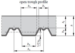
For open profiles, their effective width should be taken as the mean width. |
| b0 is the effective width of the concrete ribs, |
taken as |
|
mm |
|
|
|
|
For re-entrant profiles, the minimum width should be used. |
| dp is the depth to the centroidal axis, |
taken as |
|
mm |
|
|
|
|
|
| |
|
|
|
|
|
|
|
|
|
| 3) Longitudinal shear check |
|
| For longitudinal shear, it is assumed that there is no end anchorage, so that clause 9.7.3 is applicable. |
|
| a) m-k method |
|
|
|
|
|
|
|
|
| The design shear resistance is: |
|
|
|
|
|
|
|
|
| |
 |
|
kN/m |
|
|
|
|
|
|
| The value used are: |
|
|
|
|
|
|
|
|
| |
b = |
1.0 |
m |
|
dp = |
|
mm |
|
|
| |
Ls = l/4 = |
0 |
mm |
|
Ap = |
|
mm2 |
|
|
| |
m = |
|
N/mm2 |
|
k = |
|
N/mm2 |
|
|
| This value must not be exceeded by the vertical shear in the slab. Therefor, Vl,Rd is taken as: |
|
| |
 |
|
kN/m |
< |
VEd= |
|
kN/m |
Recalculate |
If this method is not verified longitudinal shear check, uses partial connection theory |
| |
|
|
|
|
|
|
|
|
|
| Serviceability limit state |
|
| Control of cracking of concrete |
|
| As the slab is designed as simply supported, only anti-crack reinforcement is needed. The cross-sectional area of the reinforcement above the ribs should be not less than 0.2% for un-propped construction. |
|
| |
min As = 0.002 x b x hc = |
|
mm2/m |
|
|
|
|
|
|
| and the A252 mesh used here is sufficient. |
with As = 252 mm2/m |
(f8 a200) |
|
|
|
|
|
| |
|
|
|
|
|
|
|
|
|
| Deflection |
|
| Second moment of area |
|
| The short-term elastic moduli and modular ratios are: |
|
| |
 |
|
|
|
|
|
|
|
|
| For buildings, EN 1994 permits the simplification that all strains may be assumed to be twice their short-term value. |
|
| The long-term elastic moduli and modular ratios are: |
|
| |
 |
|
|
|
|
|
|
|
|
| The depth of neutral axis (counted from the top of slab) is then given by the 'first moments of area' equation: |
See R.P.JOHNSON's books |
| |
 |
|
|
|
|
|
|
|
|
| Hence |
 |
|
mm |
|
|
|
|
|
|
| The second moment of area is: |
|
| |
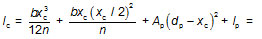 |
|
mm4/m |
|
|
|
|
|
|
| The total load is taken as, using the frequent combination for calculating the deflection of composite slab: |
|
| |
 |
|
kN/m2 |
|
|
|
|
|
|
| |
|
|
|
|
|
|
|
|
|
| For the calculation of delecftion, firstly, the slab is considered to be simply supprted. |
|
| The mid-span deflection is: |
|
|
|
|
|
|
|
If the deflection is greater than the limit value, recalculate as the continuous slab. |
| |
 |
|
mm |
|
|
|
|
|
|
| The allowable deflection is: |
|
|
|
|
|
|
|
A more accurate calculation for the continuous slab, assuming 15% of each span to be cracked |
| |
 |
|
mm |
< |
 |
|
mm |
Recalculate |
|
| |
|
|
|
|
|
|
|
|
|
| All design checks are OK at both the ultimate limit state and the serviceability limit state. |
|
| |
|
|
|
|
|
|
|
|
|