| Verification for composite stage |
| |
| Section classification |
| The parameter e : |
 |
ε= |
|
|
|
|
| Outstand of compression flange |
 |
c= |
|
mm |
|
|
| |
c/tf= |
|
|
|
|
| |
9ε= |
|
|
The limiting value for class 1 |
|
| |
10ε= |
|
|
The limiting value for class 2 |
|
| |
14ε= |
|
|
The limiting value for class 3 |
|
| |
|
|
|
|
|
| Internal compression part: |
 |
c= |
|
mm |
|
|
| |
c/tw= |
|
|
|
|
| |
72ε= |
|
|
The limiting value for class 1 |
|
| |
83ε= |
|
|
The limiting value for class 2 |
|
| |
124ε= |
|
|
The limiting value for class 3 |
|
| |
|
|
|
|
|
| The class of the cross-section is Class 1 |
|
|
| Effective width of concrete flange |
| At the midspan: |
 |
beff= |
|
m |
Section with equal concrete flange. |
nr=1, b0=0 |
| |
 |
be= |
|
m |
|
nr=2, b0=100mm |
| |
|
|
|
|
|
|
| Design shear resistance of a headed stud |
| The design shear resistance of a shear connector is |
 |
PRd1= |
|
kN |
|
 |
|
PRd2= |
|
kN |
|
 |
hsc/d= |
|
|
|
| α= |
|
|
Check |
| |
γv= |
|
|
|
| For sheeting with ribs transverse to the supporting beam, the reduction factor for shear resistance is: |
 |
kt= |
|
|
Assumption for tranverse ribs arrangement |
| |
kmax= |
|
|
|
nr=2, kmax=0.70 |
| nr= |
|
|
Input data |
|
| kt= |
|
|
|
|
| The design shear resistance should be determined by: |
 |
PRd= |
|
kN |
|
|
| |
|
|
|
|
|
|
| Degree of shear connection |
| Number of shear connectors studs for half span: |
 |
n= |
|
|
|
nr=2, n is even number |
| Total resistance of shear connectors |
 |
Nq= |
|
kN |
|
|
| Compression resistance of concrete slab |
 |
Ncf= |
|
kN |
P.N.A in steel beam |
|
| Tensile resistance of the steel section |
 |
Npl,a= |
|
kN |
|
|
| Degree of shear connector: |
 |
η= |
|
|
Partial shear connection |
|
| Checking the condition of minimum degree of partial shear connection |
|
|
|
|
|
| The minimum degree of shear connection is |
 |
ηmin≥ |
|
|
Recalculate |
if the connection is full shear connection, not check it |
| |
|
|
|
|
|
|
| Verification of bending resistance (plastic resistance moment) |
| Total loads (factored load used for ULS): |
|
w= |
|
kN/m |
|
|
| The mid-span bending moment is: |
 |
MEd= |
|
kNm |
|
|
| The design vertical shear is: |
 |
VEd= |
|
kN |
|
|
| Interpolation method: |
|
|
|
|
|
|
| Concrete flange resistance with partial shear connection |
 |
Nc= |
|
kN |
|
if the connection is full shear connection, calculate next part |
| Plastic moment capacity of steel section |
 |
Mpl,a,Rd= |
|
kNm |
|
| MRd could be defined from the interpolated equation: |
 |
|
|
|
|
| Mpl,Rd is plastic moment resistance with full shear connection. |
| |
 |
Npl,a'= |
|
kN |
|
P.N.A in concrete slab  |
| Check the P.N.A |
|
|
|
|
|
P.N.A in steel flange  |
| |
|
|
|
|
P.N.A in steel web  |
| The depth of plastic neutral xpl |
|
xpl= |
|
mm |
|
P.N.A in concrete slab   |
| the resistance moment in full shear connection is |
|
Mpl,Rd= |
|
kNm |
|
P.N.A in steel flange   |
| The resistance moment MRd with patial shear connection is |
 |
MRd= |
|
kNm |
|
P.N.A in steel web 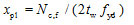  |
| Check |
|
MRd |
< |
MEd |
recalculate |
|
| |
|
|
|
|
|
|
| Verification of vertical shear resistance |
| The shear area of the steel beam is |
 |
Avz= |
|
mm2 |
|
EN 1994-1-1 6.2.1.3 (3) |
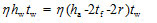 |
ηhwtw= |
|
mm2 |
|
|
| |
η= |
|
|
|
|
| |
Avz= |
< |
ηhwtw |
Take the larger one |
|
| Shear plastic resistance |
 |
Vpl,a,Rd= |
|
kN |
|
|
| |
Vpl,a,Rd |
< |
VEd |
recalculate |
|
| Note that the verification to shear buckling is not required when: |
 |
hw/tw= |
|
|
|
|
| 72ε/η= |
|
|
|
|
| |
|
hw/tw |
> |
72ε/η |
verification to shear buckling is required |
| Note that the reduction in bending resistance is not required when: |
 |
VEd/Vpl,a,Rd= |
|
|
ok, reduction to bending resistance is not required |
| |
|
|
|
|
|
|
| Longitudinal Shear resistance |
| Transverse reinforcement |
| The plastic longitudinal shear stresses is given by: |
 |
vEd= |
|
N/mm2 |
|
|
 |
△x= |
|
m |
|
|
 |
△Fd= |
|
kN |
|
|
| To prevent crushing of the compression struts in the concrete flange, the following condition should be satisfied: |
 |
vfcdsinθfcosθf= |
|
N/mm2 |
|
|
 |
v= |
|
|
|
|
| |
θf= |
|
|
Input data |
|
| |
vfcdsinθfcosθf |
< |
vEd |
Recalculate |
|
| Continuous profiled decking with ribs perpendicular to the beam span |
 |
|
|
|
|
|
| In practice, it is usual to neglect the decking |
 |
|
|
|
|
|
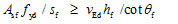
| the area of transverse reinforcement per unit length is |
 |
Asf/sf ≥ |
|
mm2/m |
|
|
| The reinforcement provided is |
|
As= |
|
mm2/m |
recalculate |
|
| Diameter of reinofrcement bars |
|
d= |
|
mm |
Input data |
|
| Space |
|
s= |
|
mm |
Input data |
|
| |
|
|
|
|
|
|
| Serviceability limit state verification |
| The modula ratio for variable loading is n0, and the modular ratio for permanent load is around 3n0. But, for simplicity, creep will be allowed for by using n = 2n0 for all loading. |
| |
 |
n= |
|
|
|
|
| Distance from the top surface of the concrete slab to centre of area |
 |
zg= |
|
mm |
|
|
| The neutral-axis depth is given by |
|
|
|
|
|
for the neutral-axis depth x to be less than hc  |
| |
x= |
|
mm |
|
  |
| The second moment of area is: |
|
I= |
|
cm4 |
|
for the neutral-axis depth x to be larger than hc  |
| The deflection of steel beam due to permanent load is |
|
δa= |
|
mm |
|
|
| The deflection of composite beam is |
 |
δc= |
|
mm |
|
  |
| The total deflection is |
|
δ= |
|
mm |
|
|
| Allowable deflection is: |
 |
[δ]= |
|
mm |
|
|
| Check |
|
δ |
> |
[δ] |
recalculate |
|
| |
|
|
|
|
|
|