| Design of Concrete Filled Rectangular tubes |
| Type |
Data |
Check |
Reference |
| Composite column specifications |
|
| |
Column length |
L= |
|
m |
Input data |
 |
| |
Effective length y-y |
Ley= |
|
m |
|
| |
Effective length z-z |
Lez= |
|
m |
|
| |
Column Type |
Fully Encased |
|
| Design value of actions |
| |
Design axial force |
Nsd= |
|
kN |
Input data |
| |
Design bending moment |
|
|
|
|
| |
about y-y (major) axis |
My,top,sd= |
|
kNm |
Input data |
| |
|
My,bot,sd= |
|
kNm |
Input data |
| |
about z-z (minor) axis |
Mz,top,sd= |
|
kNm |
Input data |
| |
|
Mz,bot,sd= |
|
kNm |
Input data |
| |
| Material properties |
| Structural steel |
|
Choose the steel grade |
|
| |
Characteristic yield strength |
fy= |
|
N/mm2 |
|
|
| |
Modulus elastic of steel |
Ea= |
|
N/mm2 |
|
|
| |
Partial safety factor |
Ya= |
|
|
|
|
| |
Design strength |
fyd= |
|
N/mm2 |
|
|
| |
|
|
|
|
|
|
| Concrete |
|
|
|
|
|
| |
Concrete grade |
|
Choose the concrete grade |
|
| |
Type of concrete |
Normal Weight Concrete |
|
|
| |
Characteristic value of compressive strength |
fck= |
|
N/mm2 |
|
|
| |
Partial safety factor |
Yc= |
|
|
|
|
| |
Design value of compressive strength |
fcd= |
|
N/mm2 |
|
|
| |
Secant modulus of elasticity |
Ecm= |
|
N/mm2 |
|
|
| |
|
|
|
|
|
|
| Reinforcement |
|
|
|
|
|
| |
Characteristic yield strength |
fyk= |
|
N/mm2 |
Input data |
|
| |
Partial safety factor |
Yc= |
|
|
|
|
| |
Design yield strength |
fsd= |
|
N/mm2 |
|
|
| |
Design value of modulus of elasticity |
Es= |
|
N/mm2 |
|
|
| |
|
|
|
|
|
|
| Connectors |
|
|
|
|
|
| |
Diameter |
d= |
|
mm |
Input data |
|
| |
Overall nominal height |
hsc= |
|
mm |
Input data |
|
| |
Ultimate tensile strength |
fu= |
|
N/mm2 |
Input data |
|
| |
|
|
|
|
|
|
| Cross section geometry and section propertises of the selected section |
| Structural Steel |
|
Choose the steel |
|
| |
Mass |
m= |
|
kg/m |
|
|
| |
Depth |
h= |
|
mm |
|
|
| |
Width |
b= |
|
mm |
|
|
| |
Thickness |
t= |
|
mm |
|
|
| |
Root radius |
r= |
|
mm |
|
|
| |
Section area |
Aa= |
|
cm2 |
|
|
| |
Second moment of area /yy |
Iay= |
|
cm4 |
|
|
| |
Elastic modulus /yy |
Wel,y= |
|
cm3 |
|
|
| |
Plastic modulus /yy |
Wpl,y= |
|
cm3 |
|
|
| |
Second moment of area /zz |
Iaz= |
|
cm3 |
|
|
| |
Elastic modulus /zz |
Wel,z= |
|
cm3 |
|
|
| |
Plastic modulus /zz |
Wpl,z= |
|
cm3 |
|
|
| |
check for local buckling |
h/t= |
|
|
|
|
| |
|
|
|
|
|
|
| Concrete |
|
|
|
|
|
| |
Area of concrete |
Ac= |
|
cm2 |
|
|
| |
Second moment of area about major axis: y-y (of columns) |
Icy= |
|
cm4 |
|
|
| |
Second moment of area about minor axis: z-z (of columns) |
Icz= |
|
cm4 |
|
|
| |
|
|
|
|
|
|
| Reinforcement |
|
|
|
|
|
| |
The number of longitudinal bars |
n= |
|
|
Input data |
|
| |
Bar diameter |
d= |
|
mm |
Input data |
|
| |
Total section area |
As= |
|
cm2 |
|
|
| |
Concrete cover |
|
|
mm |
Input data |
|
| |
|
ey= |
|
|
|
|
| |
|
ez= |
|
|
|
|
| |
Second moment of total area about major axis: y-y (of columns) |
Isy= |
|
cm4 |
|
|
| |
Second moment of total area about minor axis: z-z (of columns) |
Isz= |
|
cm4 |
|
|
| |
Reinforcement ratio |
As/Ac= |
|
|
|
|
| |
|
|
|
|
|
|
| |
|
|
|
|
|
|
| |
| Plastic resistance of the composite cross section to compression: |
| |
 |
Npl,Rd= |
|
kN |
|
|
| |
Steel contribution factor |
δ= |
|
|
|
|
| Checking long term loading: |
| Efective elastic flexural stiffness: |
| |
 |
Ec,ef= |
|
N/mm2 |
|
|
| |
φt= |
|
|
Input data |
|
| |
assuming permanent load is % of design load |
NG,Ed= |
|
kN |
Input data |
|
| |
About the minor axis (y-y): |
|
|
|
|
|
| |
 |
Ke= |
|
|
Input data |
|
| |
(EI)ey= |
|
kNm2 |
|
|
| |
|
|
|
|
|
|
| |
About the minor axis (z-z): |
|
|
|
|
|
| |
 |
Ke= |
|
|
Input data |
|
| |
(EI)ey= |
|
kNm2 |
|
|
| Elastic buckling load: |
| |
About the major axis (y-y): |
|
|
|
|
|
| |
 |
Ncry= |
|
kN |
|
|
| |
About the minor axis (z-z): |
|
|
|
|
|
| |
 |
Ncrz= |
|
kN |
|
|
| Plastic resistance to compression: |
| |
 |
Npl,Rk= |
|
kN |
|
|
| Non-dimesional slenderness ration: |
| |
About the major axis (y-y): |
|
|
|
|
|
| |
 |
 |
|
|
|
|
| |
About the minor axis (z-z): |
|
|
|
|
|
| |
 |
 |
|
|
|
|
| |
|
|
|
|
|
|
| Evaluate the resistance of the composite column under axial compression: |
| |
Reduction factor: |
|
|
|
|
|
| |
strut curve b for major axis and strut curve c for minor axis |
|
|
|
|
|
| |
y-y axis |
|
|
|
|
|
| |
 |
ay= |
|
|
Input data |
|
| fy= |
|
|
|
|
| χy= |
|
|
|
|
| |
|
|
|
|
| |
z-z axis |
az= |
|
|
Input data |
|
| |
|
fz= |
|
|
|
|
| |
|
χz= |
|
|
|
|
| |
Where: a is the imperfection parameter which allows for different levels of imperfections in the columns |
|
| |
|
|
|
|
|
|
| |
|
 |
|
|
|
|
| |
|
|
|
|
|
|
| Checking Resistance of composite section to under combined compression |
| |
Major axis bending (y-y): |
|
|
|
|
|
| |
Wps: Plastic section modulus for reinforcement |
|
|
|
|
|
| |
 |
Wps= |
|
cm3 |
|
|
| |
Wpsn: Plastic section modulus for reinforcement within the region of 2hn from the middle line |
|
|
| |
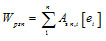 |
Wpsn= |
|
cm3 |
Check |
|
| |
Neutral axis position: |
|
|
|
|
|
| |
 |
hn= |
|
mm |
|
|
| |
ez= |
|
mm |
|
|
| |
|
|
|
|
|
|
| |
Wpc: Plastic section modulus for concrete: |
|
|
|
|
|
| |
 |
Wpc= |
|
cm3 |
|
|
| |
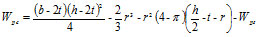
Wpan: Plastic section modulus of steel within the region of 2hn from the middle line: |
|
|
| |
 |
Wpan= |
|
cm3 |
|
|
| |
Wpcn: Plastic section modulus of concrete within the region of 2hn from the middle line: |
|
|
| |
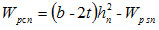 |
Wpcn= |
|
cm3 |
|
|
| |
The bending resistance |
|
|
|
|
|
| |
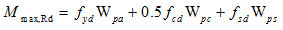 |
Mmax,Rd= |
|
kNm |
|
|
| |
 |
Mpl,Rd= |
|
kNm |
|
|
| |
The resistance force |
|
|
|
|
|
| |
 |
Npm,Rd= |
|
kN |
|
|
| |
|
|
|
|
|
|
| Interaction Diagram: |
| |
Major axis bending (y-y) |
|
|
|
|
|
| |
|
|
|
|
|
|
| Point |
|
|
|
|
|
|
| A |
Bending Moment M (kNm) M=0 |
MA= |
|
kNm |
|
|
| Compression force N (kN) N=Npl,Rd |
NA= |
|
kN |
|
|
| B |
Bending Moment M (kNm) M=Mpl,Rd |
MB= |
|
kNm |
|
|
| Compression force N (kN) N=0 |
NB= |
|
kN |
|
|
| C |
Bending Moment M (kNm) M=Mpl,Rd |
MC= |
|
kNm |
|
|
| Compression force N (kN) N=Npm,Rd |
NC= |
|
kN |
|
|
| D |
Bending Moment M (kNm) M=Mpm,Rd |
MD= |
|
kNm |
|
|
| Compression force N (kN) N=0.5Npm,Rd |
ND= |
|
kN |
|
|
| |
|
|
|
|
|
|
| |
|
|
|
|
|
|
| |
|
|
|
|
|
|
| |
Minor axis bending (z-z): |
|
|
|
|
|
| |
Wps: Plastic section modulus for reinforcement |
|
|
|
|
|
| |
 |
Wps= |
|
cm3 |
|
|
| |
Wpsn: Plastic section modulus for reinforcement within the region of 2hn from the middle line |
|
|
| |
 |
Wpsn= |
|
cm3 |
|
|
| |
Neutral axis position: |
|
|
|
|
|
| |
 |
hn= |
|
mm |
|
|
| |
ey= |
|
mm |
|
|
| |
Wpc: Plastic section modulus for concrete: |
|
|
|
|
|
| |
 |
Wpc= |
|
cm3 |
|
|
| |
Wpan: Plastic section modulus of steel within the region of 2hn from the middle line: |
|
|
| |
 |
Wpan= |
|
cm3 |
|
|
| |
Wpcn: Plastic section modulus of concrete within the region of 2hn from the middle line: |
|
|
| |
 |
Wpcn= |
|
cm3 |
|
|
| |
The bending resistance |
|
|
|
|
|
| |
|
Mmax,Rd= |
|
kNm |
|
|
| |
|
Mpl,Rd= |
|
kNm |
|
|
| |
The resistance force |
|
|
|
|
|
| |
|
Npm,Rd= |
|
kN |
|
|
| |
|
|
|
|
|
|
| Interaction Diagram: |
|
|
| |
Minor axis bending (z-z) |
|
|
|
|
|
| |
|
|
|
|
|
|
| Point |
|
|
|
|
|
|
| A |
Bending Moment M (kNm) M=0 |
MA= |
|
kNm |
|
|
| Compression force N (kN) N=Npl,Rd |
NA= |
|
kN |
|
|
| B |
Bending Moment M (kNm) M=Mpl,Rd |
MB= |
|
kNm |
|
|
| Compression force N (kN) N=0 |
NB= |
|
kN |
|
|
| C |
Bending Moment M (kNm) M=Mpl,Rd |
MC= |
|
kNm |
|
|
| Compression force N (kN) N=Npm,Rd |
NC= |
|
kN |
|
|
| D |
Bending Moment M (kNm) M=Mpm,Rd |
MD= |
|
kNm |
|
|
| Compression force N (kN) N=0.5Npm,Rd |
ND= |
|
kN |
|
|
| |
|
|
|
|
|
|
| |
|
|
|
|
|
|
| |
|
|
|
|
|
|
| Checking for combined compression and bending: |
| |
 |
(EI)eff,II,y= |
|
kNm2 |
|
|
| |
 |
(EI)eff,II,z= |
|
kNm2 |
|
|
| |
|
Ke,II= |
|
|
Input data |
|
| |
|
Ko= |
|
|
Input data |
|
| |
|
|
|
|
|
|
| |
 |
Ncr,eff,y= |
|
kN |
|
|
| |
 |
Ncr,eff,z= |
|
kN |
|
|
| |
for end moment |
β= |
|
|
Input data |
|
| |
 |
k1,y= |
|
|
|
|
| |
k1,z= |
|
|
|
|
| hence |
for bending moment from menber imperfection |
β= |
|
|
Input data |
|
| |
|
k2,y= |
|
|
|
|
| |
|
k2,z= |
|
|
|
|
| |
|
e0,y= |
|
m |
|
|
| |
|
e0,z= |
|
m |
|
|
| |
 |
My,Ed= |
|
kNm |
|
|
| |
|
μdy Mpl,y,Rd= |
|
kNm |
|
|
| |
|
|
|
|
as shown in interaction curve |
|
| |
|
My,Ed/μdyMpl,y,Rd = |
|
|
|
|
| |
|
αM= |
|
|
Input data |
|
| |
|
|
|
|
|
|
| |
 |
Mz,Ed= |
|
kNm |
|
|
| |
|
μdz Mpl,z,Rd= |
|
kNm |
|
|
| |
|
|
|
|
as shown in interaction curve |
|
| |
|
Mz,Ed/μdzMpl,z,Rd = |
|
|
|
|
| |
|
αM= |
|
|
Input data |
|
| |
|
|
|
|
|
|
| |
 |
|
|
|
|
|
| |
|
|
|
imperfection only considered in plane in which failure is expected to occur. |
| Vertical shear |
| |
major axis y-y |
|
|
|
|
|
| |
The vertical shear is |
|
|
|
|
|
| |
 |
Vy,Ed= |
|
kN |
|
|
| |
The design shear resistance is |
|
|
|
|
|
| |
 |
Vpl,a,Rd,y= |
|
kN |
|
|
| |
|
|
|
|
|
|
| |
Minor axis z-z |
|
|
|
|
|
| |
 |
Vz,Ed= |
|
kN |
|
|
| |
 |
Vpl,a,Rd,z= |
|
kN |
|
|
| |
|
|
|
|
|
|
| Longitudinal shear |
| |
longitudinal shear force is |
|
|
|
|
|
| |
 |
NEd,c= |
|
kN |
|
|
| |
longitudinal shear stress |
|
|
|
there is no well-established method for calculating longitudinal shear stress, usually based on |
| |
 |
 |
|
N/mm2 |
|
|
| |
perimeter of steel section |
pa= |
|
mm |
|
|
| |
load introduction length |
lv= |
|
mm |
|
|
| |
design shear strength |
 |
|
N/mm2 |
|
|
| |
if  |
|
|
|
|
|
| |
 |
PRd1= |
|
kN |
|
|
| |
 |
PRd2= |
|
kN |
|
|
| |
 |
hsc/d= |
|
|
|
|
| |
α= |
|
|
|
|
| |
|
PRd= |
|
kN |
|
|
| |
number of headed studs |
|
|
|
|
|
| |
|
n= |
|
|
|
|